- Loading accuracy as high as + 1%
- Straining at variable speeds to suit a wide range of materials. Printer & PC graphs enables to study the behavior of the material.
- Motor driven threaded columns for quick effortless adjustment of lower cross-head-to facilitate rapid fixing of test specimen.
- Simplicity in reading because of digital readouts.
- Wide range of standard and special accessories, including load stabilizer
- Easy change from plain to threaded and screwed specimens.
- Large effective clearance between columns enables testing of standards specimens as well as structures.
- Simple controls for ease of operation.
- Robust straining frame of an extremely rigid construction. Safe operation ensured by means of safety devices.
- Fully enclosed and protected pressure transducer.
- RS 232 serial port to transfer data to computer for analysis/storage evaluation etc.
- Manual control & release valve operation.
- Load Capacity: 100 kN, 200 kN, 400 kN, 600 kN, 1000 kN, 1200 kN, 1500 kN, and 2000 kN.
We are Supplier, Services Provider of Electronic Universal Testing Machines and our set up is in Pune, Maharashtra, India
Application :
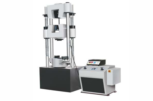
Electronic Universal Testing Machine is designed for testing Ferrous & Non-Ferrous materials under tension, compression bending, transverse and shear loads. Hardness test on metals can also conducted.
Machine Consists of –
Straining unit :
This consists of a cylinder motor with chain and sprocket drive and a table coupled with the ram of the hydraulic cylinder,
mounted on to a robust base.
The cylinder and the ram are individually lapped to eliminate friction. The upper cross-head is rigidly fixed to the table by
two strengthened columns.
The lower cross-head is connected to two screwed columns which are driven by a motor. Axial loading of the ram is
ensured by relieving the cylinder and ram of any possible side loading by the provision of ball seating.
A Rotary Encoder of minimum resolution 0.1mm is provided to measure the deformation of the specimen.
Tension test is conducted by gripping the test specimen between the upper and lower cross-heads.
Compression, transverse, bending, shear and hardness tests are conducted between the lower cross-head and the
table.
The lower cross-head can be raised or lowered rapidly by operating the screwed columns, thus facilitating ease of fixing
of the test specimen.
Control Panel:
The Control Panel consists of a power pack complete with drive motor and an oil tank, control valves and electronic
display unit.
Power Pack:
The power pack generates the maximum pressure of 200 kgf/cm2.
The hydraulic pump provides continuously non-pulsating oil flow. Hence the load application is very smooth.
Hydraulic Controls:
Hand operated wheels are used to control the flow to and from the hydraulic cylinder.
The regulation of the oil flow is infinitely variable. Incorporated in the hydraulic system is a regulating valve, which
Maintains a practically constant rate of piston movement.
Control by this valve allows extensometer reading to be taken.
Principle of Operation for - Model: UTE
Operation of machine is by hydraulic transmission of load from the test specimen through pressure transducer to a
separately housed load indicator.
The system is ideal since it replaces transmission of load through levers and knife edges, which are prone to wear and
damage due to shock on rupture of test pieces.
Load is applied by a hydrostatically lubricated ram.
Main cylinder pressure is transmitted to the pressure transducer housed in the control panel.
The transducer gives the signal to the electronic display unit, corresponding to the load exerted by the main ram.
Simultaneously the encoder fitted on the straining unit gives the mechanical displacement to the electronic display unit.
Both the signals are processed by the microprocessor and load and displacement is displayed on the digital readouts
simultaneously.
Electronic Control Panel (Series Universal 2001-UTE):
Microprocessor based panel incorporating state of art technology with following features -
- Front panel membrane type key board for machine operation with numeric keys for data entry.
- 7 segment display.
- Data entry with numeric key board of test parameters including speeds, rupture % peak, pre-load, modulus data, test data & specimen data etc.
- 20 input data set storage, 50 result storage, maintains data and results during power off.
Accuracy and Calibration:
Electronic Universal testing machine is closely controlled for sensitivity, accuracy and calibration during every stage of manufacture. Machine is calibrated over each of its measuring range in accordance with the procedure laid down in IS 1828: Part1: 1991. Electronic Universal Testing Machine complies with Grade “A” of class 1 of IS-1828-Part1:1991.

Optional Software Package - Tension & Compression test Software package for Model : UTE.
Input Data

Control Parameters
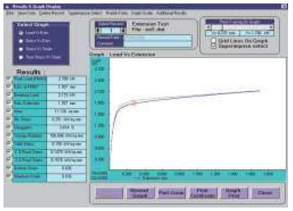
Load Vs Extension

Displays graph for extensometer readings against load with proof lines for proof stress.
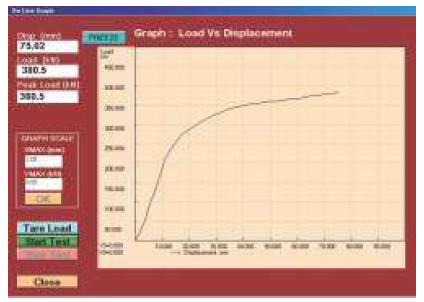
Real Time Graph

Real time values of load & displacement/extension used for plotting its graph & can be seen real time during testing.
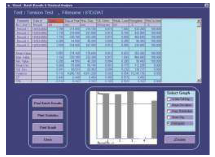
Statistics

Batch test reports with statistics for batch sample results.
Graph Superimpose with Point Tracing

Graph comparison, superimpose of batch sample tests with point tracing facility.
Windows based software available for -
Online graph on PC, Data analysis, Statistics,
Point tracing, superimposing graphs to compare
with standard, zooming graph etc.


