
We are Supplier, Services Provider of Compression Testing Machines and our set up is in Pune, Maharashtra, India. We provide our whole range to ALL OVER INDIA, but; We majorly target customers from Gujrat, Ahmedabad, Surat, Rajkot, Vadodara, Anjar, Vapi, Kutch, Bhuj, Karnataka, Bengaluru, Hubballi, Dharwad, Belgaum, Maharashtra
- Loading accuracy as high as + 1%.
- Straining at variable speeds to suit a wide range of materials.
- Continous roll autographic recorder supplied as standard to enable study of the behaviors of materials.
- High reading accuracy due to large size and design of dial.
- Wide range of standard and special accessories, including load stabilizer.
- Large effective clearance between columns enables testing of standard specimen as well as structures.
- Simple controls for ease of operation.
- Robust straining frame of an extremely rigid construction.
- Safe operation ensured by means of safety devices.
Application :
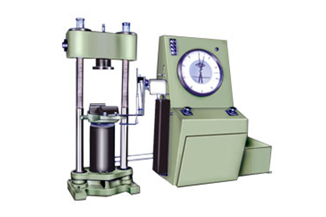
Compression Testing Machine is designed to test materials and other materials under compression, bending, transverse and shear loads. Hardness test on metals can also be conducted.
Principal of Operation :
Operation of the machine is by hydraulic transmission of load from the test specimen to separately housed load indicator. The hydraulic system is ideal since it replaces transmission of load through levers and knife edges, which are prone to wear and damage due to shock on rupture of test pieces.
Load is applied by a hydrostatically lubricated ram. Main cylinder pressure is transmitted to the cylinder of the pendulum dynamometer system housed in the control panel. The cylinder of the dynamometer is also of self-lubricating design. The piston of the dynamometer is constantly rotated to eliminate friction. The load transmitted to the cylinder of the dynamometer is transferred through a lever system to a pendulum. Displacement of the pendulum actuates the rack and pinion mechanism which operates the load indicator pointer and the autographic recorder. The deflection of the pendulum represents the absolute load applied on the test specimen.
Return movement of the pendulum is effectively damped to absorb energy in the event of sudden breakage of a specimen.
Machine consists of :
Straining Unit :
This consists of a hydraulic cylinder and a table coupled with the ram of hydraulic cylinder, mounted on robust base. The cylinder and the ram are individually lapped to eliminate friction. The cross-head is connected to two screwed columns and is driven by a motor, for rapid adjustment of test height.
An elongation scale with a minimum graduation of 1.0 mm, is provided to measure the deformation of the specimen.
Compression, transverse, bending, shear and hardness tests are conducted between the lower cross head and the table.
Control Panel :
The control Panel consists of a power pack complete with drive motor and an oil tank, control valves a pendulum dynamometer a load indicator system and an autographic recorder.
Power Pack :
The power pack generates the maximum pressure of 200 kgf/cm2. The hydraulic pump provides continuously no pulsating oil flow. Hence the load application is very smooth.
Hydraulic Controls :
Hand operated wheels are used to control the flow to and from the hydraulic cylinder. The regulation of oil flow is infinitely variable. Incorporate in the hydraulic system is a regulation valve, which maintains a practically constant rate of table movement.
Load Indicator System :
This system consists of a large dial and a pointer. A dummy pointer is provided to register the maximum load reached during the test. Different measuring ranges can be selected by operating the range selection knob.
An overload trip switch is incorporated which automatically, cuts out the pump motor when the load range in use is exceeded.
Pendulum Dynamometer :
This unit permits selection of favorable hydraulic ratios producing relatively small frictional forces. Pressurized oil in the loading cylinder pushes up the measuring piston proportionately and actuates the special dynamometer system. The piston is constantly rotated to eliminate friction. The dynamometer system is also provided with an integral damper and ensures high reliability of operation. The load transmitted to the dynamometer is transferred through a pendulum to the load indicator.
Autographic Continuous Roll Load-Elongation Recorder :
This unit is of the pen and drum type and is supplied as standard. The horizontal motion of the pen produces the load ordinate of the diagram and the drum rotation produces the extension ordinates in the ratio of either 1:5 or 1:10.
A continuous roll of graph paper is stored inside the drum and is easily replaced.
Accuracy & Calibration :
AII Compression Testing Machines are closely controlled for sensitivity, accuracy and calibration during every stage of manufacture. Every machine is then calibrated over each of its measuring ranges in accordance with the procedure laid down in BS : 1610 and IS : 1828, FIE Compression Testing Machines comply with Grade "A" of BS : 1610 and class 1 of IS 1828.
An accuracy of + 1.0% is guaranteed from 20% from 20% of the load range selected to full load. Below 20% of the selected range, the maximum permissible error is 0.2% of the full load reading.
Specification :
Model |
- |
CTM 50 |
CTM 100 |
CTM 200 |
CTM 300 |
CTM 500 |
Maximum capacity |
kN |
500 |
1000 |
2000 |
3000 |
5000 |
1st Measuring Range |
kN |
0-500 |
0-1000 |
0-2000 |
0-3000 |
0-5000 |
| Minimum Graduations | kN |
1 |
2 |
4 |
5 |
10 |
2nd Measuring Range |
kN |
0-250 |
0-500 |
0-1000 |
0-1500 |
0-2500 |
Minimum Graduations |
kN |
0.5 |
1 |
2 |
2.5 |
5 |
3rd Measuring Range |
kN |
0-100 |
0-250 |
0-500 |
0-600 |
0-1000 |
Minimum Graduations |
kN |
0.2 |
0.5 |
1 |
1 |
2 |
4th Measuring Range |
kN |
0-50 |
0-100 |
0-250 |
0-300 |
0-500 |
Minimum Graduations |
kN |
0.1 |
0.2 |
0.5 |
0.5 |
1 |
Number of division on load measuring dial |
500 |
500 |
500 |
600 |
500 |
|
Maximum Clearance for compression test at fully descended working piston |
mm |
500 |
500 |
700 |
700 |
1000 |
Ram stroke |
mm |
100 |
100 |
150 |
150 |
250 |
Connected Load |
- |
- |
- |
- |
- |
- |
Power |
kW | 1.12 |
1.5 |
2.2 |
4.5 |
4.5 |
V |
- |
400-440 |
400-440 |
400-440 |
400-440 |
400-440 |
Ø |
- |
3 |
3 |
3 |
3 |
3 |
Weight |
- |
- |
- |
- |
- |
- |
(Approx.) |
tonne |
2 |
2.2 |
3.6 |
8.9 |
13 |
Special Accessories :
These include load stabilizer, Brinell test attachment, Bend Test attachment, Shear Test attachment and a wide range of accessories offered on request at additional cost.
Installation :
It is recommended that machines be erected on a foundation. Details on foundation can be given on request.
FIE reserves the rights of change in the above specifications due constant improvement in design. The dimensions given above are all approximate.