
with Microprocessor Based Measuring Panel ( Hard Bearing Models - HDCM )
We are Supplier, Services Provider of Dynamic balancing Machines and our set up is in Pune, Maharashtra, India. We provide our whole range to ALL OVER INDIA, but; We majorly target customers from Gujrat, Ahmedabad, Surat, Rajkot, Vadodara, Anjar, Vapi, Kutch, Bhuj, Karnataka, Bengaluru, Hubballi, Dharwad, Belgaum, Maharashtra
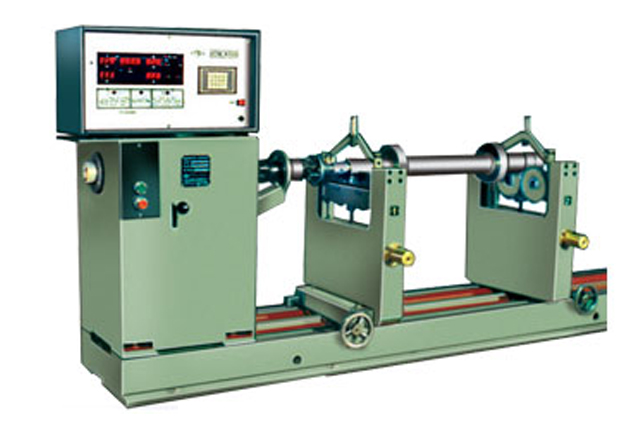
Machines Model HDM are horizontal type universal hard bearing balancing machines provided with Microprocessor based measuring panel HDM-8500 for balancing different shapes of rotors like rotors of electrical machines, crankshafts, cylinders, Gas Compressors, flywheels, turbine rotors, rotors of centrifugal pumps and any other type of rotors of rotating machines.
These machines features a very simple operation. The working cycle is fully automatic. From safety point of view a double press push button starts machine, measures and stores the unbalance values on DPMs for two planes simultaneously and stops machine ( with brake if machine is provided with electrical breaking facility.) The measuring cycle general is less than 10 seconds for normal rotors, which can be accelerated within 5 seconds.
To have smooth and gradual acceleration models HDM 3,000/ 7,000/ 10,000/ 20,000/ are provided with slipring motors in order not to have damage to drive couplings as well other rotating parts in drive systems like gears etc. The starting of these machines is done manually by cutting resistances of starter in 4 to 5 steps.
Key-board facility provided on measuring panel for correct data feeding of rotor with 1 digit accuracy for its dimensions like A, B, C, R1 & R2. Tolerance limits of both correction planes i.e. t1 and t2 can be fed, so that when rotor is balanced within the limits respective LEDs glow up, indicating no further correction necessary. For other details please refer 'Features of Measuring panel HDM-8500'.
The usable length of machine is established according to the longest roter to be balanced. Extension beds can be supplied on request, which can be added to standard bed of machine. It is also possible to install an additional bed ( Gap bed ) with a pit between this bed and standard bed of machine in order to balance rotors having its outside diameter exceeding swing over standard bed. Models HD 7,000/ 10,000/ 20,000 are provided with fixed separate drives and hence gap-bed design is not possible.
Additional Features on Demand :
Printer :
FIE Software specially developed for balancing of 2/4/6
throw crankshafts available on request.
A matrix printer can be connected through available 'FIE' software.
See sample printout. It shows trial runs till rotor is balanced within balancing tolerance.
 Dynamic Balancing Machines with Microprocessor Based Measuring Panel (Hard Bearing Model-HDM)
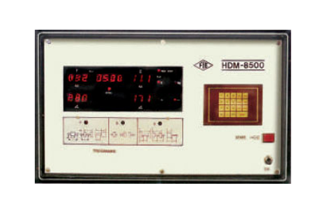 This is a microproceser based measuring panel suitable for FIE Hard Bearing Balancing Machine
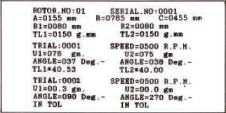
Standard Features :
• Digital display for unbalance indication
Amount and angle for unbalance for both planes displayed on separate DPMs.
Hence linear accuracy is very goos as compared to analog meter +digit for amount and + degree for angle.
• Digital display for RPM indication
A DPM is provided to indicate balancing speed continuously as a standard feature.
• Auto Stop
No necessity to stop machine once started. It stops automatically after stabilization of unbalance results.
• Simultaneous Indication
Amount and angle of unbalance in both planes displayed simultaneously and remains displayed (stored ) till next run.
This totally eliminates operation of plane selector and reduces additional time for stabilization of readings in other plane.
• Key-Board
Data of rotor dimensions and balancing tolerance i.e. values of A, B, C, R1, R2, t11, t12 are fed by key operation.
Hence accuracy of data feedings accurate up to 1 digit.
• Tolerance Indicators
Separate LEDs are provided for both planes which glow when unbalance is reduced within balancing tolerance.
• Auto Range
Depending upon whether unbalance amount is more or less a respective course or fine range gets automatically selected till rotor gets balanced within tolerance limits, Multiplier operation is totally eliminated.
• Data store
Data is provided with 'Self check' mode which checks proper functioning of digital display. LED's is cycle operation.
This helps immediate fault detection.
• Self Check
Panel is provided with ‘self-check’ mode which checks proper functioning of digital displays, LEDs is cyclic operation (optional).
This helps immediate fault detection.
Models |
Unit |
HDM-10 |
HDM-30 |
HDM-50 |
HDM-100 |
HDM-300 |
HDM-650 |
HDM-1000 |
HDM-3000 |
HDM-7000 |
HDM-10000 |
HDM-20000 |
Weight of rotor |
kg |
0.5-10 |
1-30 |
2-50 |
3-100 |
10-300 |
20-650 |
10-1000 |
30-3000 |
70-7000 |
100-10000 |
200-20000 |
Max. weight on each pedestal |
kg |
7.5 |
22.5 |
30 |
75 |
180 |
480 |
600 |
1,800 |
5,250 |
6,000 |
12000 |
Max. diameter of rotor over bed |
kg |
600 |
600 |
600 |
1,000 |
1,000 |
1,200 |
1,600 |
2000 |
2400 |
2400 |
3000 |
Max. Distance measured from coupling end to extreme bearing center. |
mm |
480 |
480 |
1,100 |
1,350 |
1350 |
1650 |
1,650 |
2,400 |
3,300 |
3,300 |
3,200 |
Min. Distance between Roller bearing of pedestals |
mm |
75 |
75 |
75 |
90 |
110 |
300 |
350 |
500 |
560 |
560 |
660 |
Rotor journal dia |
mm |
5-50 |
5-50 |
5-50 |
15-80 |
20-120 |
20-120 |
25-140 |
35-200 |
55-300 |
55-300 |
70-300 |
Balancing speed (n) |
RPM |
1,000 |
700 |
700 |
600 |
500 |
350 |
300, 600 |
250, 500 |
200, 400 |
200, 400 |
200, 400 |
Power of drive motor |
HP |
0.33 |
0.75 |
0.75 |
1.5
|
3 |
5 |
7.5 |
20 Slipring |
30 Slipring |
40 Slipring |
60 Slipring |
Acceleration Capability (GD2N2) |
kgm2n2 |
0.29x10⁶ |
0.37x10⁶ |
0.37x10⁶ |
0.88x10⁶ |
3.9x10⁶ |
8.56x10⁶ |
14.12x10⁶ |
88x106 |
168x106 |
216x106 |
301x106 |
Minimum unbalance mass measured |
g |
0.01 |
0.1 |
0.1 |
0.1 |
0.1 |
0.1 |
0.1 |
0.1 |
1 |
1 |
1 |
Maximum unbalance mass measured |
kg |
4 |
4 |
4 |
4 |
4 |
4 |
4 |
4 |
40 |
40 |
40 |
Unbalance reduction ratio |
% |
95 |
95 |
95 |
95 |
95 |
95 |
95 |
95 |
95 |
95 |
95 |
Minimum achievable unbalance per Rotor Weight (for max. weight or rotor) |
gmm/kg |
0.5 |
0.5 |
0.5 |
0.5 |
0.5 |
0.5 |
0.5 |
0.5 |
0.5 |
0.5 |
0.5 |